DCF77 is a German longwave time signal and standard-frequency radio station – according to Wikipedia. It is used by most radio controlled clocks in Europe to adjust the time, after my previous post about 433 MHz devices I decided to check this out and try to make a decoder.
The data packet – although it is only 59 bits – holds a lot: the current date and time, day of week, current time zone (CET or CEST), upcoming daylight saving time change and leap seconds, civil danger/emergency warnings, weather forecast and parity bits. (The weather forecast is in a proprietary format, though, more on that later.)
It is transmitted on 77.5 kHz at a whopping 1 bit per second rate using amplitude modulation, the 59 data bits are followed by a sync period as well. The frequency is too low for my SDR so I could not catpure directly but here is a capture made using WebSDR (opened in Audacity, commented by me):
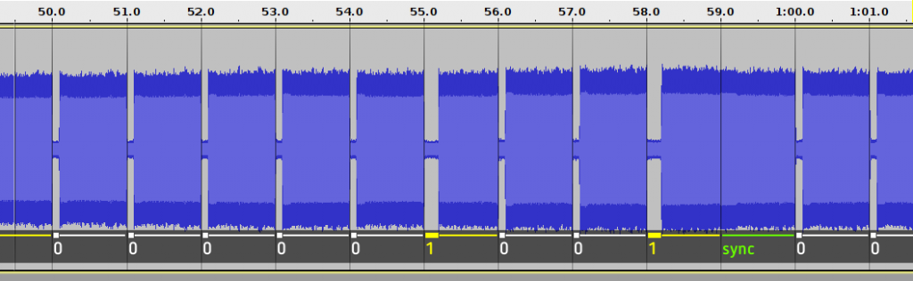
It looks clearly here there are short (100 ms) and long periods (200 ms) of low amplitude and a significantly larger period (~1800 ms) of high amplitude – according to the the specifications – they are 0 and 1 bits, and the sync signal, respectively.
The bits always start on the beginning of a second, so the data for the 1st second is always starting right at the beginning of the minute.
The format of a DCF77 packet
0-00010100101001-00010-1-1100100-1-100000-1-010010-001-10001-00000100-0-0
| |------------/ |:|:| | |-----/ | |----/ | |----/ |-/ |---/ |------/ | |
| |              |:|:| | |       | |      | |      |   |     |        | minute mark (always 0)
| |              |:|:| | |       | |      | |      |   |     |        parity for prev. section
| |              |:|:| | |       | |      | |      |   |     years
| |              |:|:| | |       | |      | |      |   months
| |              |:|:| | |       | |      | |      day of week
| |              |:|:| | |       | |      | days
| |              |:|:| | |       | |      parity for hours
| |              |:|:| | |       | hours
| |              |:|:| | |       parity for minutes
| |              |:|:| | minutes
| |              |:|:| minute start bit (always 1)
| |              |:|:leap second announcement
| |              |:|CET
| |              |:CEST
| |              |summer time announcement
| |              call bit
| civil warning bits and weather information
start of minute (always 0)

The values are encoded digit by digit in BCD:
  a b c d e f g h  =>  a*1 + b*2 + c*4 + d*8 + e*10 + f*20 + g*40 + h*80
  0 1 0 0 0 0 1 0  =>  42
  1 1 1 0 1 0 0 1  =>  97

Hours: in 24 hours format

Day of week: 1 is Monday ... 7 is Sunday

Years: within century (two digits)
More info in the GitHub repository: https://github.com/gheja/dcf77-decoder
I created a JavaScript decoder as well: https://gheja.github.io/dcf77-decoder/tools/decode_js/decode.html
Jumping on it
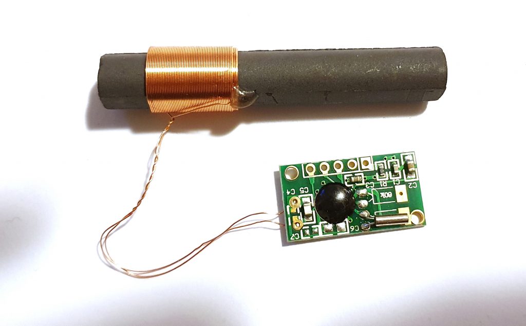
I ordered a receiver module from eBay that only converts the signal to digital levels but does not decode them – after all, that’s the fun part and I want to do that. It turned out that the low amplitude corresponds to high level, high amplitude to low level for this specific module.
In my limited experience the signal is really sensitive to noise and shielding, so it needs some work to be reliable in non-ideal conditions. For more info see Noise section below.
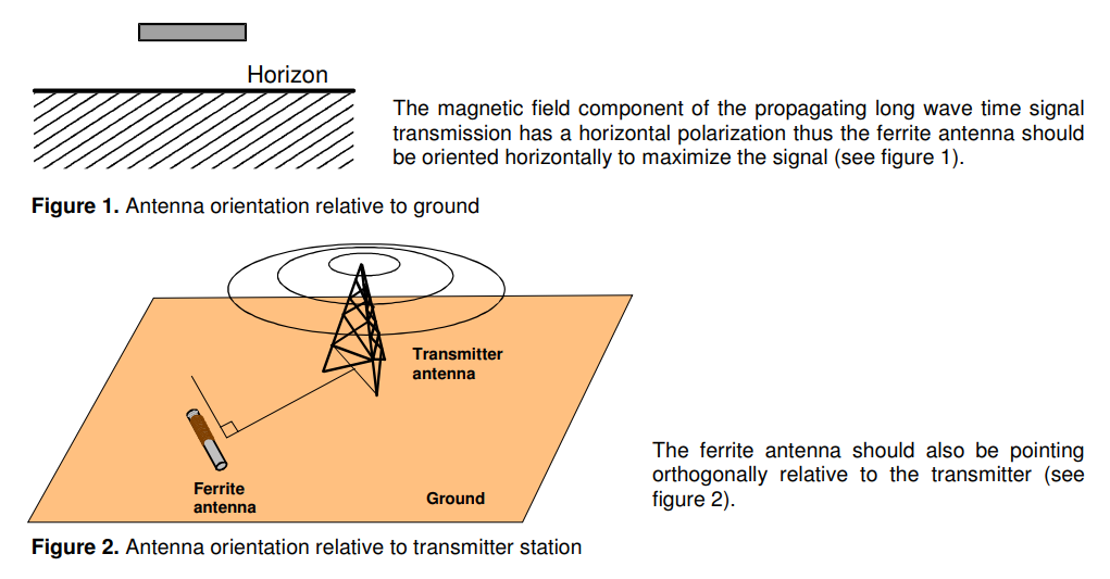
The documentation of the DCF77 receiver module has suggestions on antenna orientation as well:
Hardware
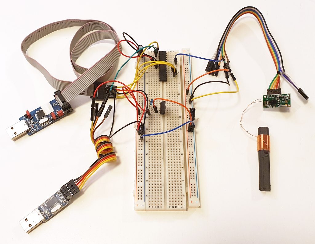
I tried to go with a simple solution but… I ended up using an ATMega328P for the microcontroller with an USBasp programmer, USB-TTL converter for communication, and the DCF77 receiver module mentioned earlier.
I read conflicting specifications for the DCF77 receiver (one stated 3.3 volts is fine, the other stated 3.0 volts as the maximum) so I added an LM317T voltage regulator to supply the 3.0 volts to it to be on the safe side (also I don’t have a spare one).
And just to be sure I don’t fry anything I always connected only one device to my computer.
Software
On the software end I decided to go with a simple state machine with the following states: waiting for signal, receiving signal. I said it’s simple (it actually had more states but they were unnecessary).
So the program reads the logic level on one pin with some basic noise reduction – read it, wait a little, repeat 200 times, assume it’s “1” if 75% of reads were “high” (confusingly meaning the received radio signal was “low”).
The program measures the length of the “high” signal so I fine-tuned (guessed) the delay above to repeat the reading and have enough precision to distinguish between the meanings:
- 0-69: invalid
- 70-84: logic 1
- 85-94: logic 0
- 95-169: invalid
- 170-189: sync
- 190+: invalid
Then based on the current state it processes the received data: if it waits for the sync and got the sync then it resets everything and switches to “receiving signal” state, if it is in receiving state it stores the bit just received.
If an error occurs anywhere (received an invalid signal) or the 59th bit is received it goes back to “waiting for sync” state. In “waiting for sync” it also checks if the data received in the last minute was valid and if it is then decodes and sends it over serial.
There is a debug option to send more detailed info over serial, see the readme for this.
I have also captured a few samples, both correct and invalid ones, check the samples.txt.
Accuracy
For the test I removed most of the messages and added a line with “!” only to be sent out as soon as sync is detected. Then checked the the accuracy of my laptop’s clock using ntpdate and on time.is, created a quick CodePen demo showing the current time and started receiving:
It turns out the time is off by around 120 milliseconds. I believe it is mostly due to my noise filtering (see Noise below) and the time it takes to transmit the data over the 9600 baud serial port. It might worth a try to tune the noise filtering but it would be much easier to just acknowledge the delay and sync the (hypothetical) other device to the received time +0.12 seconds.
Noise
We have radio controlled clocks at work and they don’t really work. They need to be placed in the windows of a specific side of the building (in the direction of the transmitter) to sync the time so they regularly take a sun bath at weekends of DST changes. And then only 90% of them syncs, the rest need manual reset and will sync overnight. Their manual recommends placing them 2 meters away from electric wiring and steel – good luck in an office, really.
I started experimenting with it in the middle of the living room, it seems to be quite noisy, but instead of moving to a more ideal location I decided to add some noise filtering in my code. It results some delay but makes the reading way more reliable.
Also, my laptop charger (while charging) adds a lot of noise, it renders about around 90% of readings unusable.
In the current version the serial port takes time to transmit the data at 9600 bits/second, in some cases longer than the pulse length of “zero” (100 ms) which prevents the correct detection of the edge.
Furhter?
That’s all for now. There are places for further optimization but I think this is enough for a proof of concept implementation.
Some interesting stuffs
Erik de Ruiter created a DCF77 Analyzer/clock that decodes and displays the data, as well as the raw bits and some more.
There are some GPS to DCF77 modules, too that create DCF77 signal based on date and time received from GPS satellites. For places with poor coverage or just fun.
The weather data is transmitted in a proprietary format, supplied by Meteotime. To decode it you need a HKW581 Meteotime decoder chip, the price includes the lifetime license.
As an interesting fact, people managed to reverse engineer the Meteotime format, an example is MeteoDecode but the keys were removed on request, also Arduino Projects4u has a description and example, too.
More
http://arduino-projects4u.com/home-weather-station/
https://github.com/ottojo/MeteoDecode
Hi,
Could you help me understand why my exact the same module as yours is giving me more than one pulse per second as output?
Sometimes even 12 pulses per second.
What is wrong?
Is there another station that I somehow receive, other than Frankfurt?
I live near Manchester UK.
Thanks,
Robert.
Hey Robert,
First of all, sorry for the very late reply…
The module I used gives only a logic high or low value, depending on the signal the antenna receives. I think in your case there is some noise which makes the read of the logic level unreliable – for the same reason I used some basic noise filtering: sampling the value from the module a number of times (200 in my case) and then assuming the signal was high if the majority (75% = 150 samples) of it were high, otherwise low. See Line 143 of my code and the Noise section of this post for more details.
And regarding the other station – I don’t think that anyone else is allowed to broadcast on this exact frequency as this station is used all around Europe.
I’m almost certain that you have finished your project a long time ago, but I wanted to reply in any case.
Gabor