The first part covers the short story of the printer, the contents of the box, a few tips and warnings about the ways you might damage your printer unintentionally (if you have not read these you should).
This part is about assembling the printer step by step.
First connect only the PSU to the controller and switch it ON and OFF, the red LED should light up when it is ON.
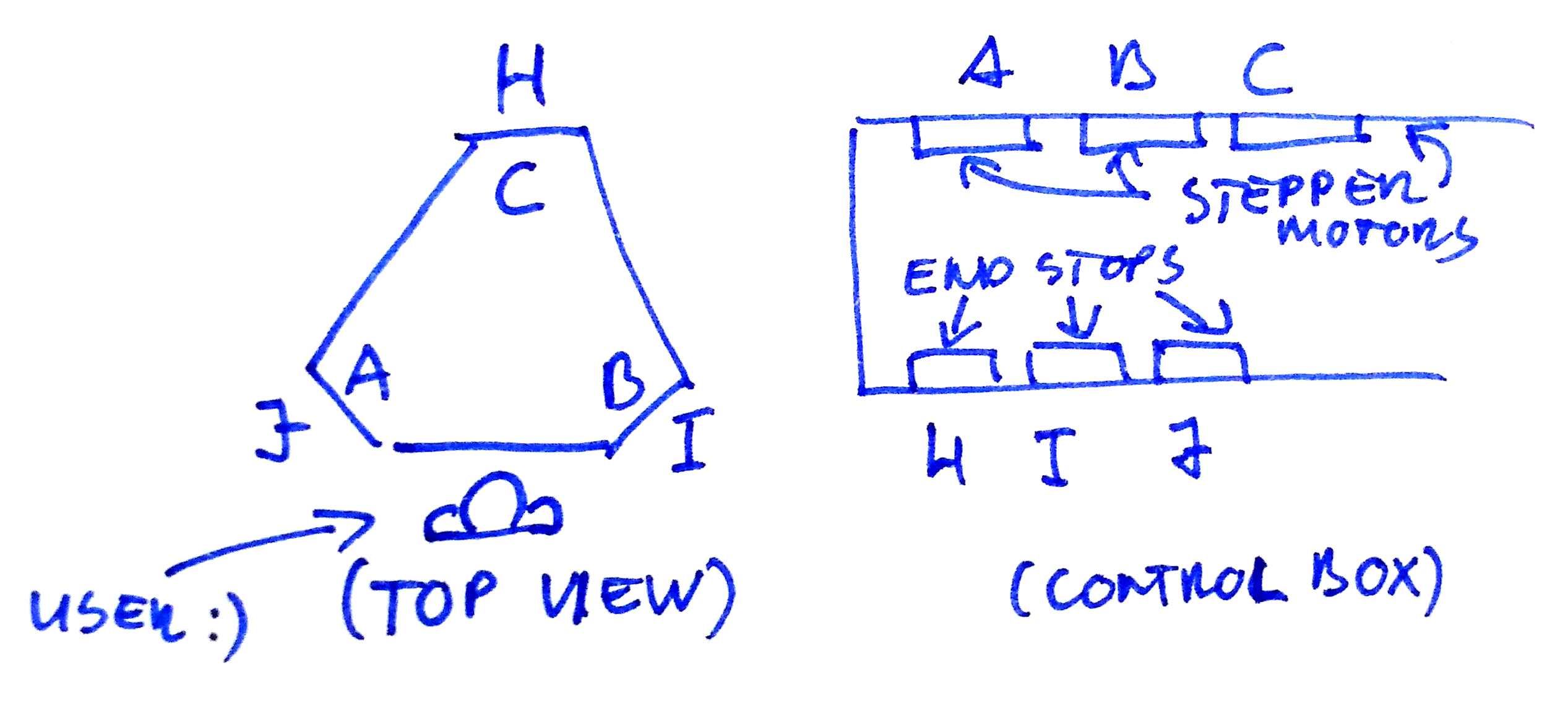
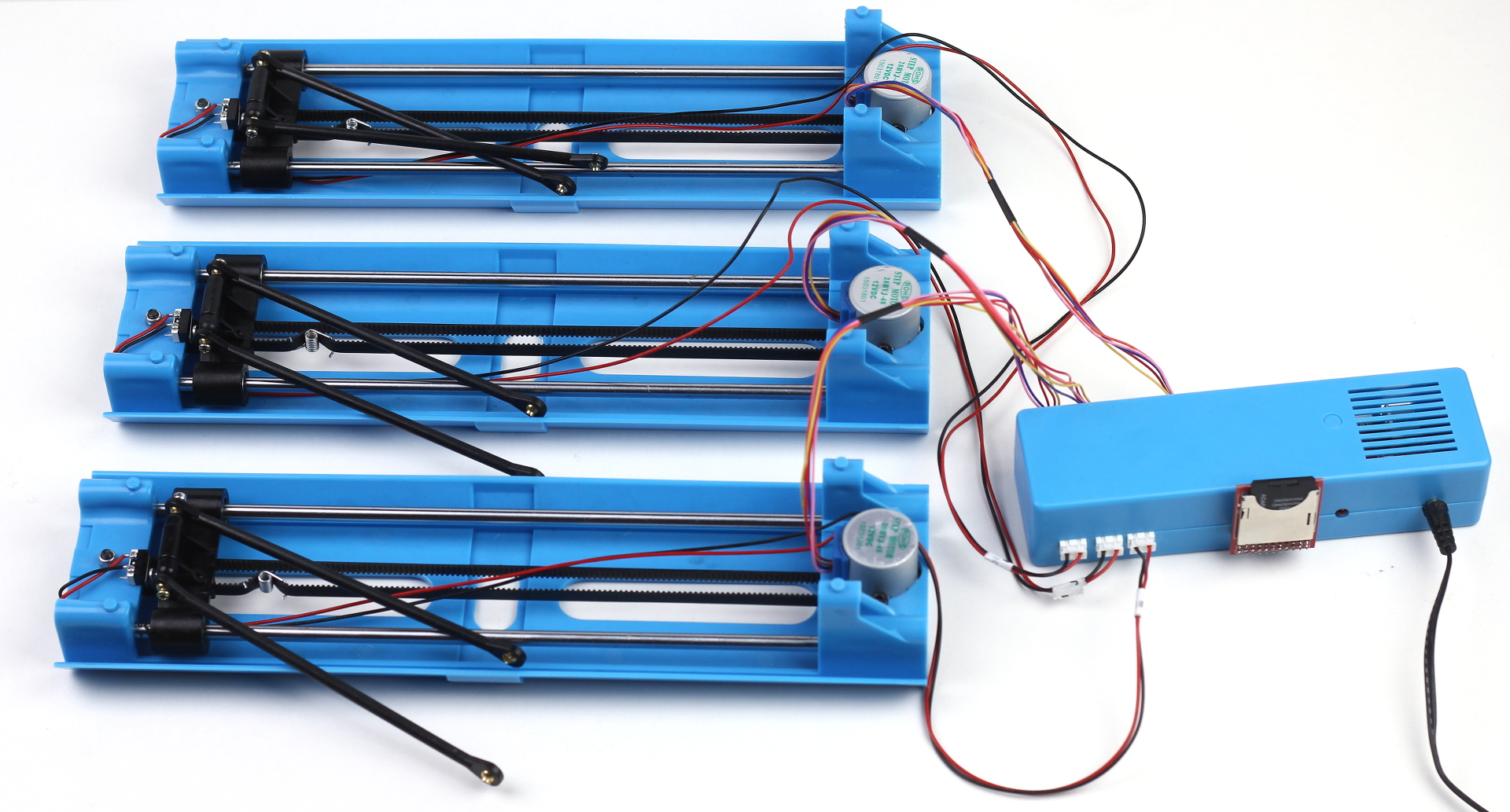
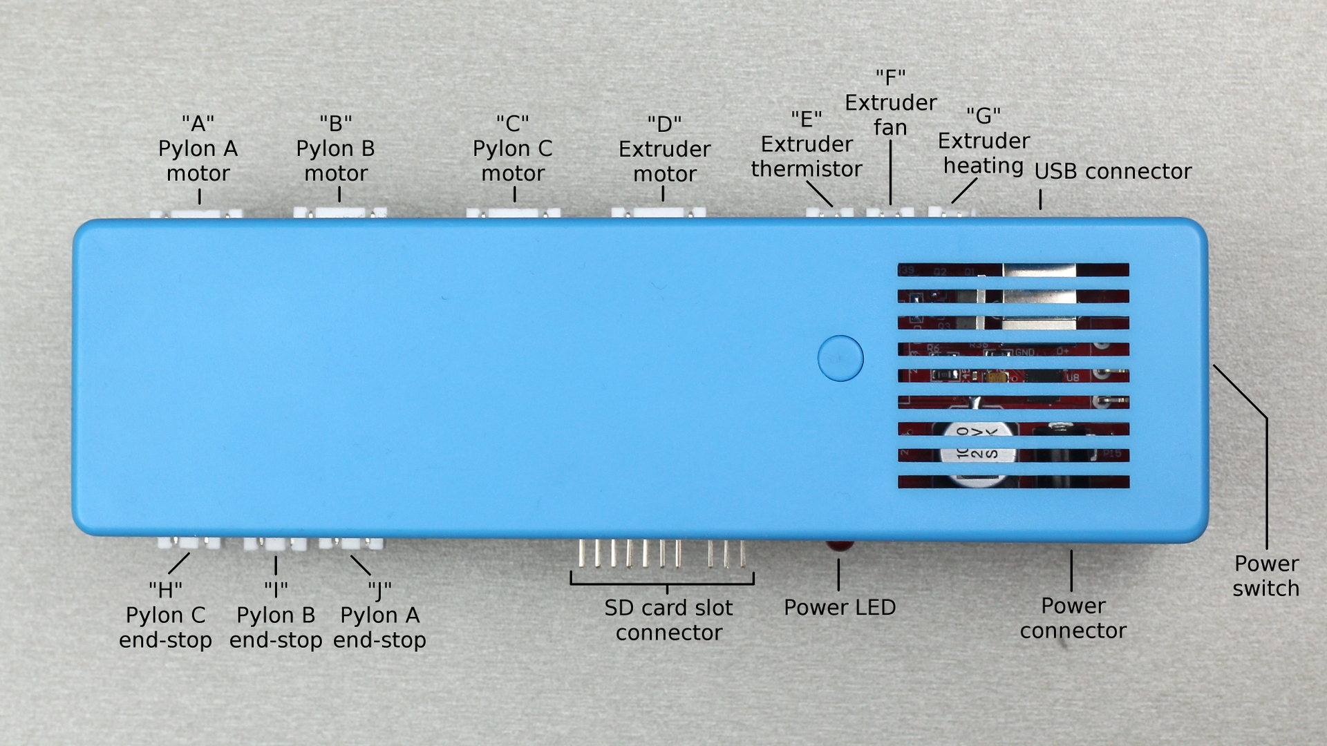
Now connect the motors and end-stops to the controller (do not assemble anything yet) and attach the SD card slot. The intended order of the pylons as well as the motor-end-stop pairings are below:
After connecting these put a simple “go home” file on your SD card and then power it up. The motors should start moving the carriages (all three at the same time) until one hits its end-stop. Then the other two should stop and only that should move back and forth triggering the end-stop a few times. After this the remaining two should do the same one by one.
If all three carriages hit the end-stops then congrats, you have working motors and end-stops, this is a good start! If not… well then you are in the unlucky group of quite a few people, including me. In this case check out the 101 Hero (Unofficial) Facebook group.
You can restart the procedure by pushing the reset button or power cycling the controller board.
Now on to assembling the printer!
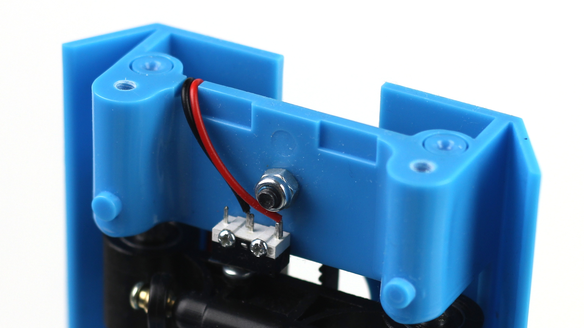
At the top of the pylon arrange the red-black cable of the end-stop so it goes through the shaft:
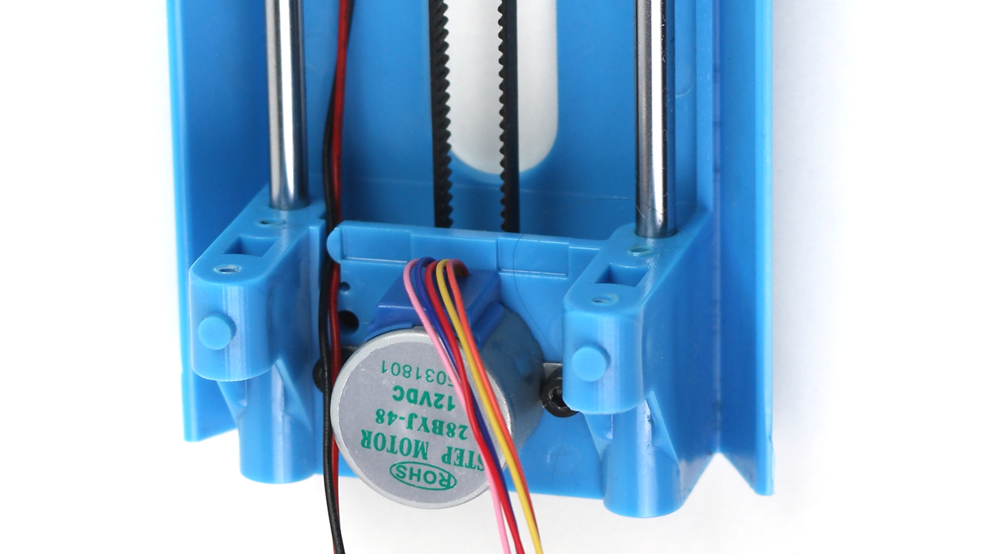
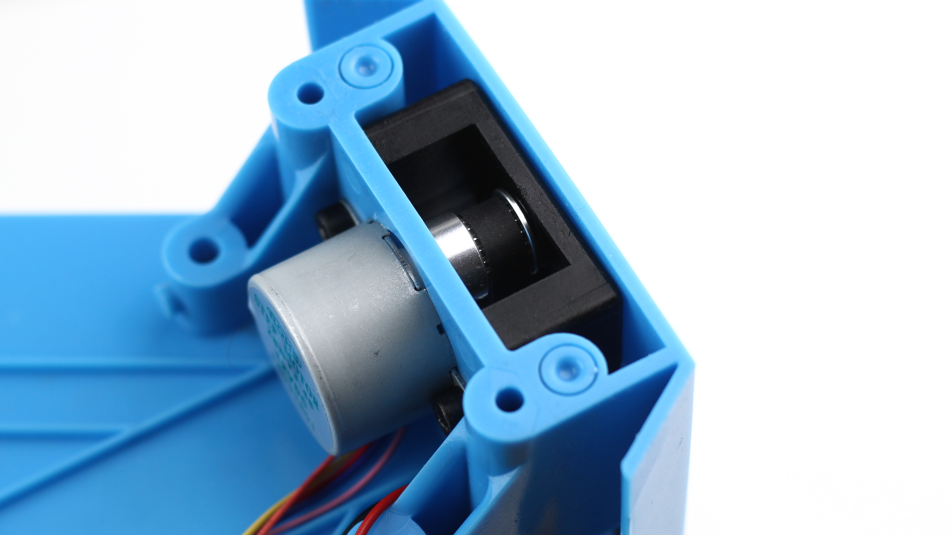
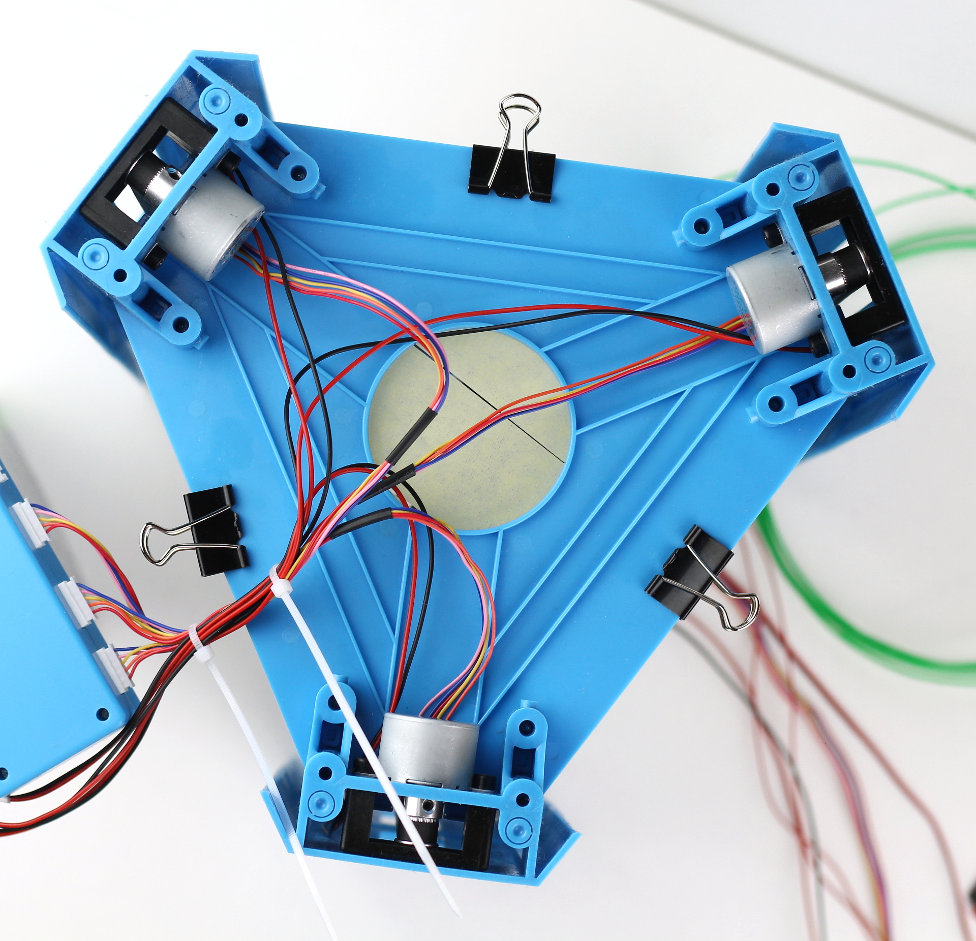
At the bottom of the pylon the red-black cable should go through the shaft just like above and arrange the cables of the motor like on the picture:
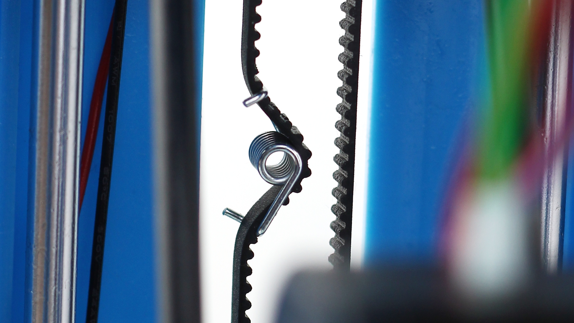
Make sure for each pylons that the spring on the belt is tight to provide tension…
… the belts are properly on the wheel at the top…
 … and the bottom:
If the belts are off the wheels try to put them back carefully. If that is not enough then you can loosen the motor a bit by loosening the two screws holding it in place (3mm Hex Socket aka Allan heads). If you have to remove the belt tensioner spring here’s a video how to put it back.
Next, assemble the bottom plate and the three pylons (4 pcs of M4x12 self-tapping screws (PH1 head) for each pylon):
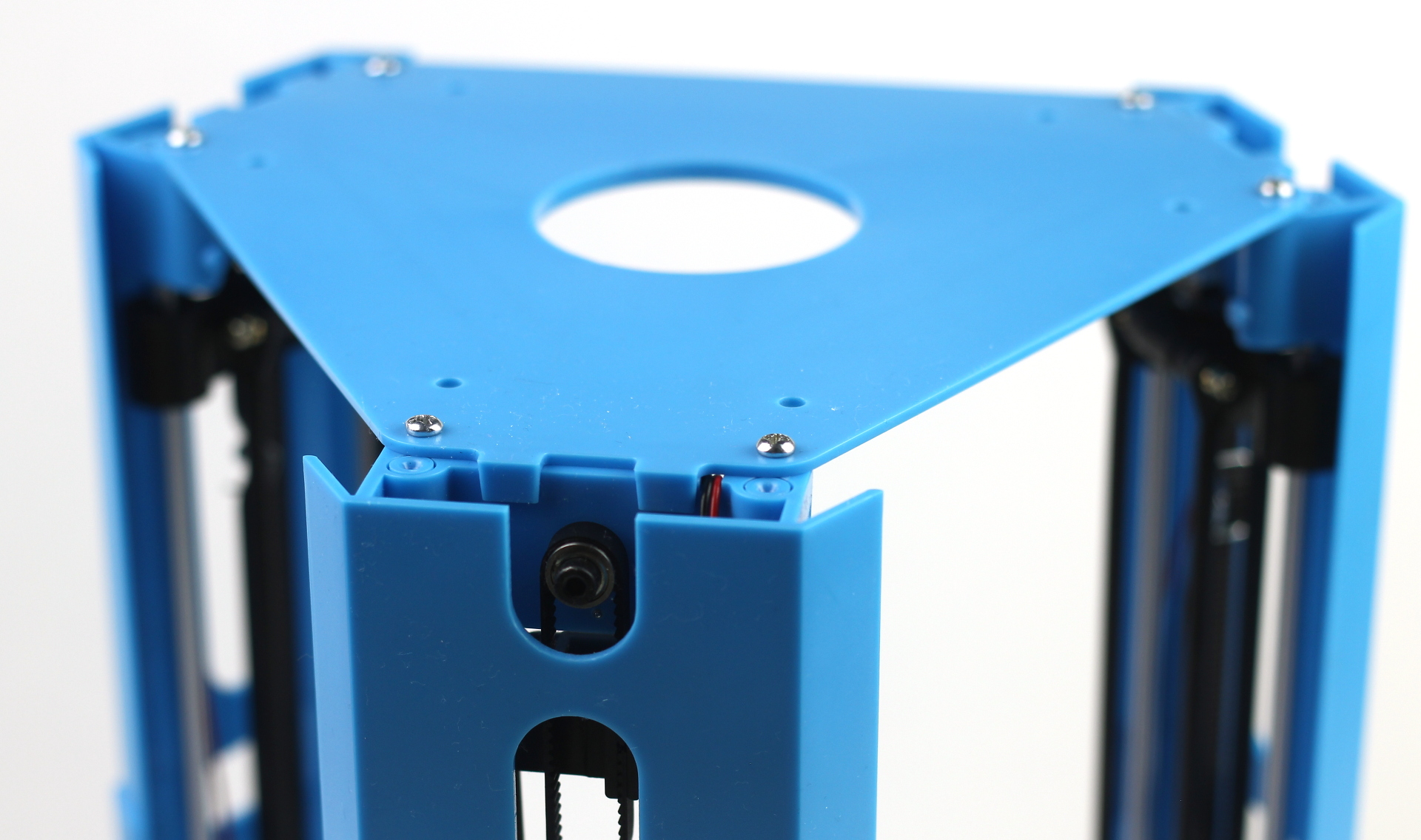
And then add the top plate (2 pcs of M4x12 self-tapping screws (PH1 head) for each pylon, NOTE: the two inner holes remain empty on each end on the top):
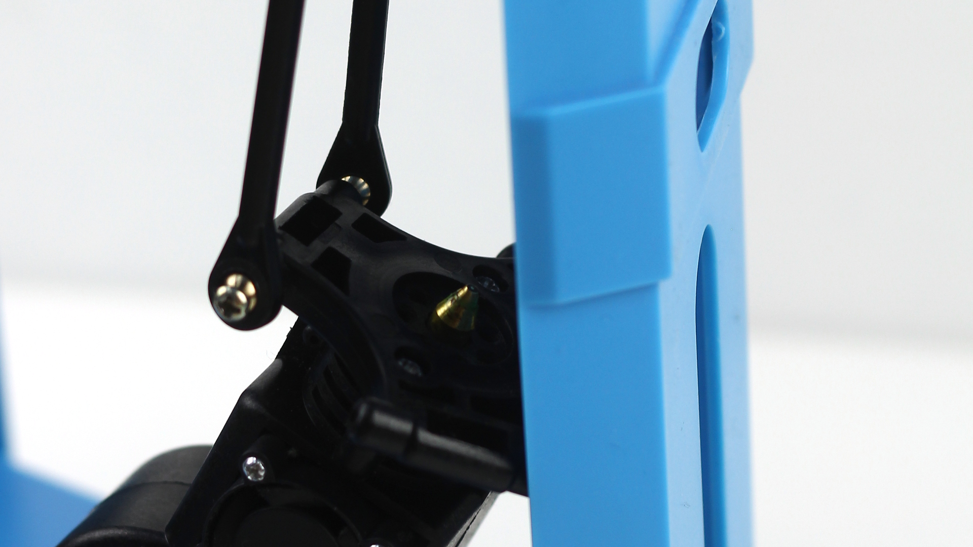
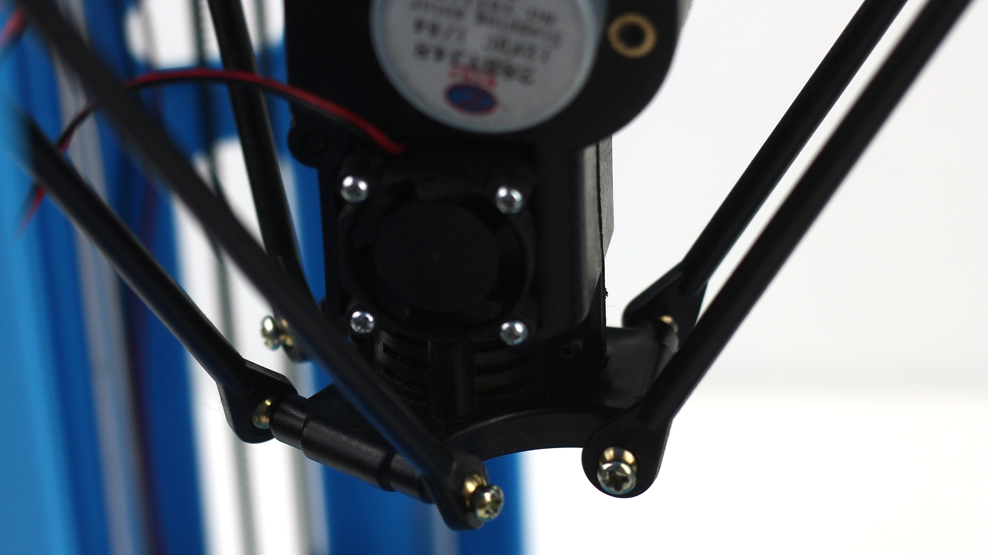
And now fix the effector to the rods. The facing of the head does not matter but it can be useful to see the fan (to see if it is working) and the door (for change filament) from the front. The first screw…

… the second screw (you can safely leave it hanging)…
… and the rest:
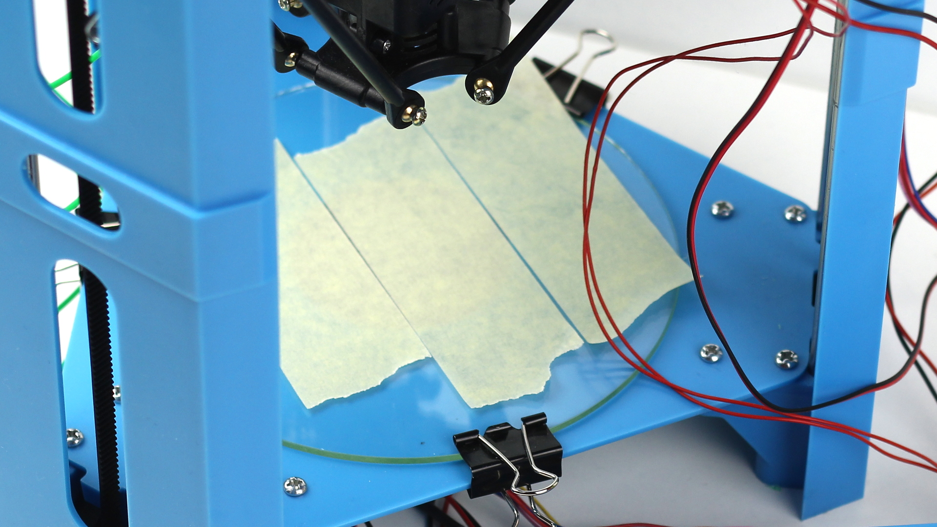
Now stick some painter’s tape to the glass plate (you don’t need to cover the whole glass just make sure you have no overlaps of the tape) put it on the bottom plate and fix it in place using the paper clips like this:
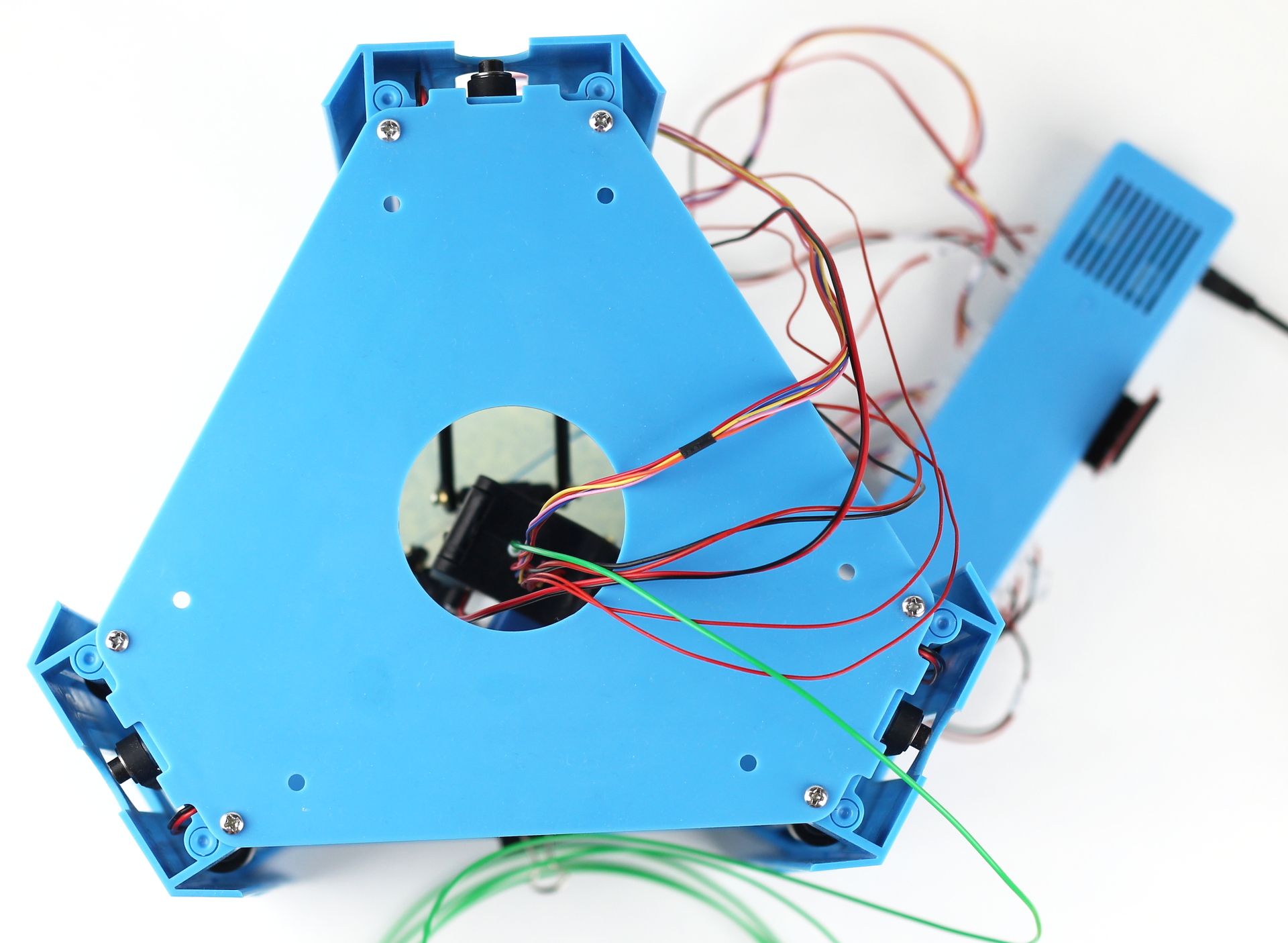
Now connect the rest of the cables to the controller box:
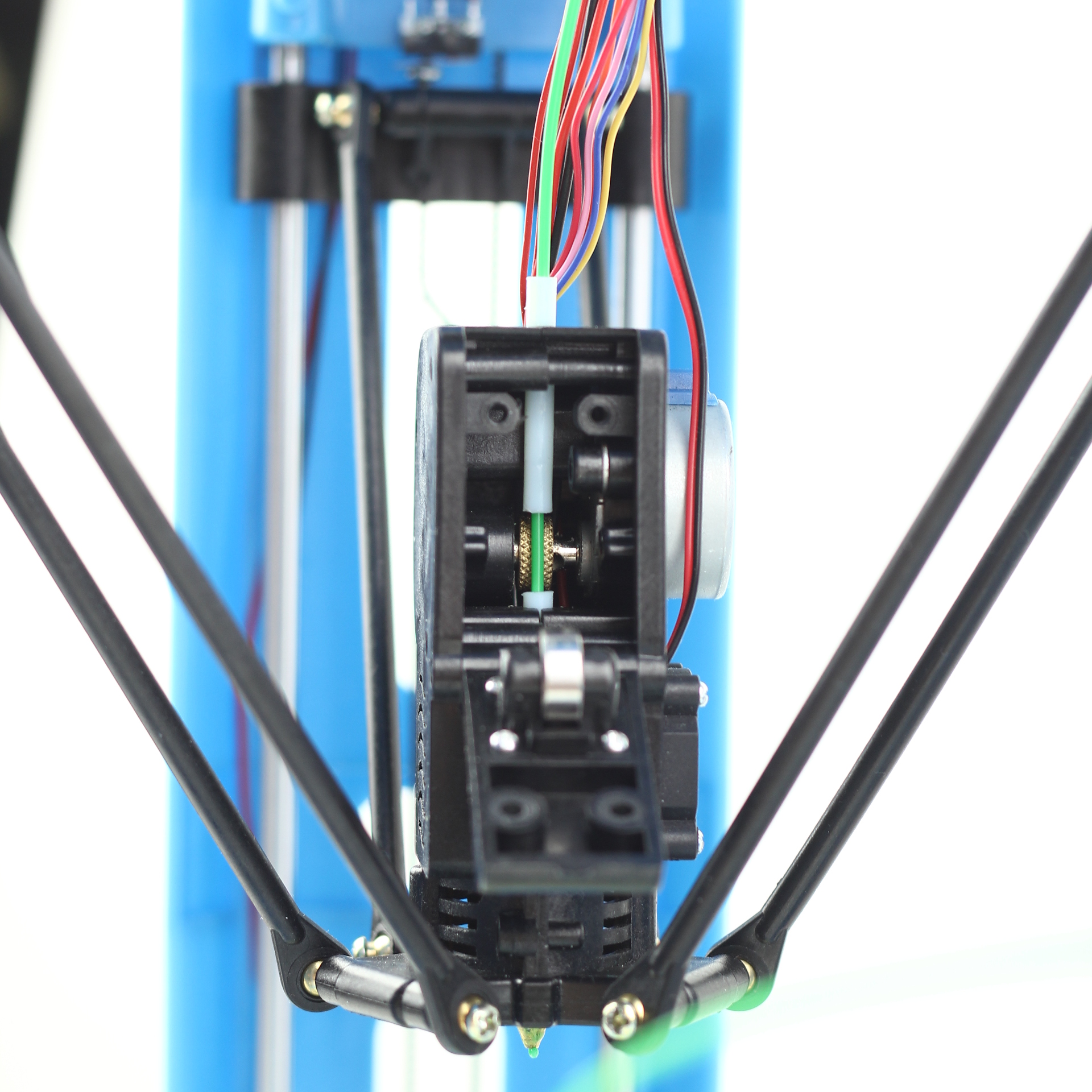
Next step is to load the filament. The extruder assembly has a door you can open, this door pushes the filament to the extruder motor which is supplying the filament to the heated nozzle. Open up the door and put the filament in at the top of the extruder assembly, guide it into the tube after the motor, like this:
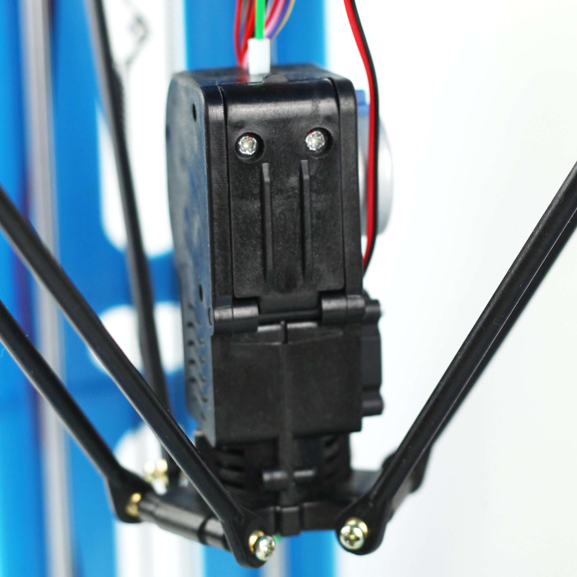
When completed close the door and tighten the screws (2 pcs M3x12 self-tapping screws (PH1 head)).
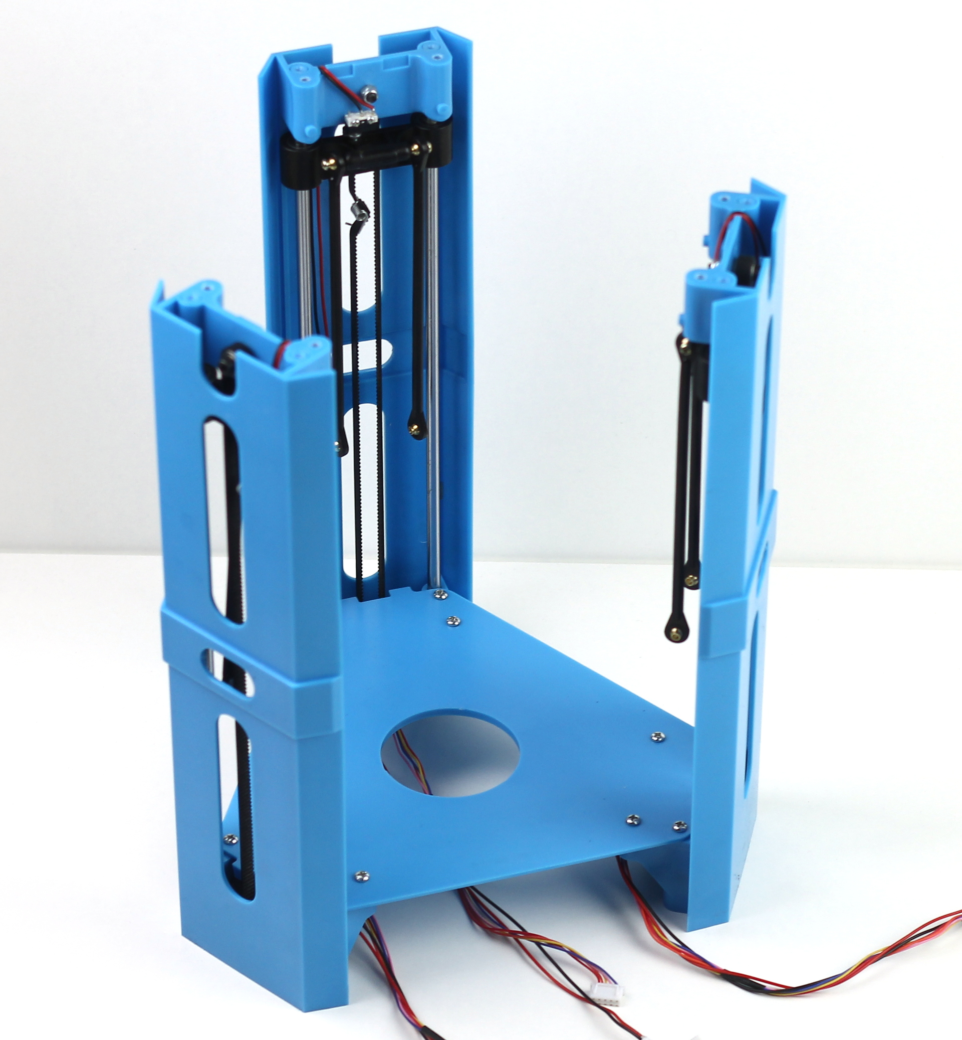
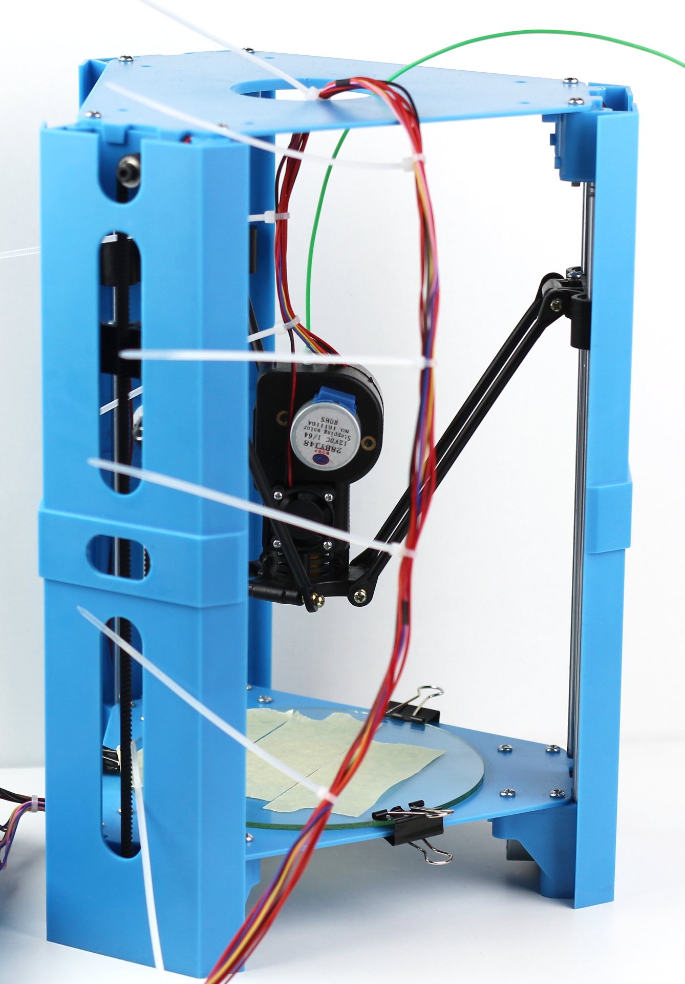
After completing this step the printer should look like this:
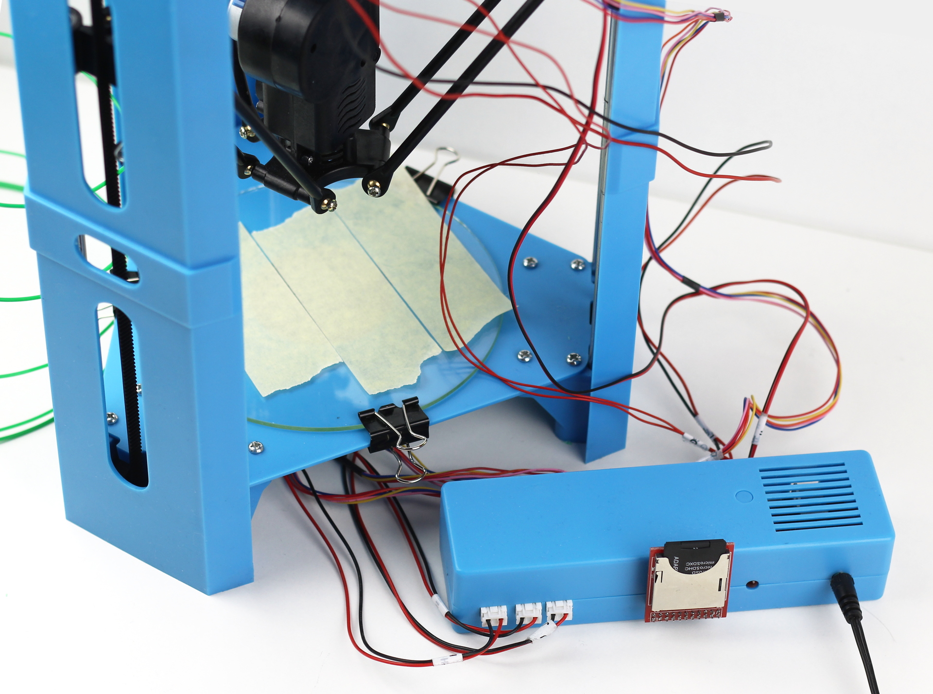
Which is a mess. The cable management is pretty much non-existent for the 101hero by default. People use different cable organizing methods, the most popular is the spiral wrap but personally I like the zip tie method which is nothing special just zip tying the cables at a few centimeters interval, like this:
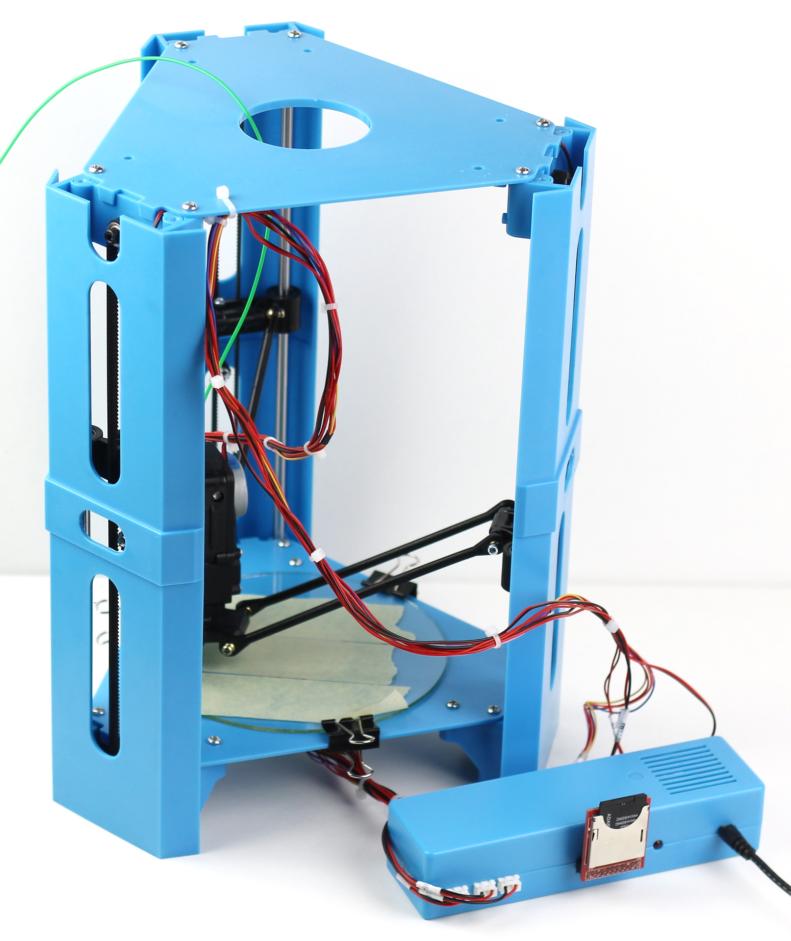
After completing this step you should cut the ties short, of course. One more thing I did was fixing the bunch of extruder cable to the top plate to an unused hole like this:
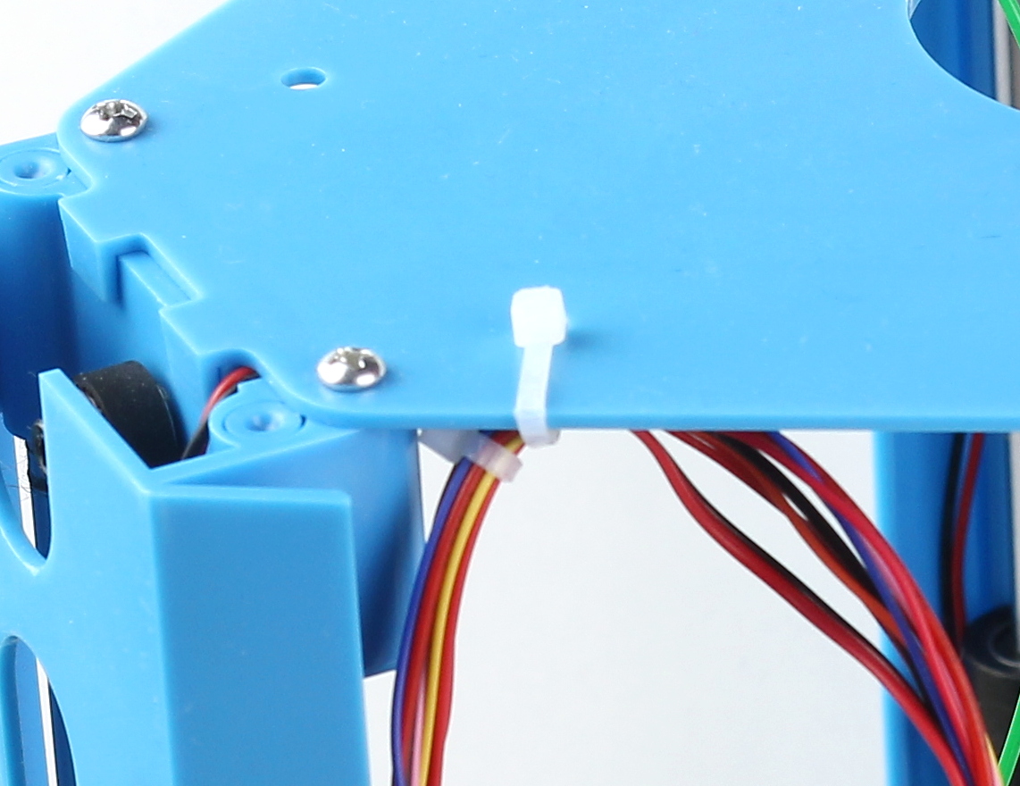
You need to leave about 25 cm (10 inches) of cable between the fixing point and the extruder assembly so the hot end can reach the farthest point safely.
And that’s all about assembling the printer. The next post will be about how to calibrate the 101hero.
For those that like things to line up nicely, Pylon C is at the top of the Y axis so if you assemble the printer with the extruder door facing away from pylon c, having the extruder open towards you will provide a top down X/Y layout of the print surface.
Pylon orientation would be C @ 12 o’clock, A @ 4 o’clock, B @ 8 o’clock.
Hey Robert!
Thanks for the comment. Though I have one suggestion, if you place the pylons in these positions then you will have mirrored prints (so from above the letter “Z” will be “S”), to prevent this you would need to swap the pylon A and B (or their connectors and end-stops on the controller board), so pylon A should be at 8 o’clock and pylon B at 4 o’clock.
Have a nice day,
Gabor